
This line following vehicle project demonstrates an approach to controlling an autonomous line-following robot using Python. By implementing a feedback loop for motor control based on sensor data, the robot can navigate effectively along a designated path.
Building and programming a line-following robot using our Robo-Tx library is not just a technical exercise; it’s a comprehensive learning experience that combines various aspects of STEM (science, technology, engineering, and mathematics). This code serves as a foundational example for those interested in robotics and automation, illustrating key programming concepts and practical applications in the field.
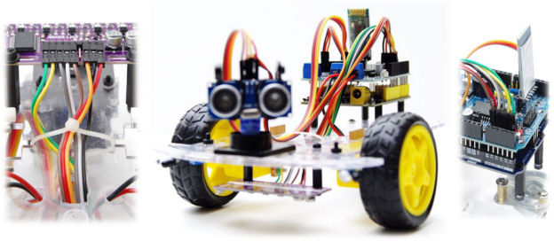
To find out more about the Robo-Tx framework, visit Python Robotics Simplified. Vehicle chassis (such as pictured above) are low cost and easily available as kits from online stores. Such kits usually consist of two motors and wheels, a nylon castor wheel, a chassis board and various fixings. Additionally, an Arduino Uno, a robotics motor expansion board, and a 7.4V LiPo battery will be needed. If not supplied with the vehicle, an HC-05 (or similar) Bluetooth module will also be required.
A five-channel digital line sensor that outputs high when a black line is detected must be connected to pins A0 to A4 of the motor expansion board, and attached underneath the vehicle. Pin A0 is connected to the left most channel, and A4 to the right most channel of the line sensor. 15mm PVC black electrical tape offers an effective way to make a path for the robotic vehicle to follow.
Download the Project Source Code and Required Utilities
Visit and review Software, Equipment and Tools for Building Robots for instructions to configure your robotics development environment. Use the links in that section to download all robotics project source code (including Robo-Tx firmware) and necessary libraries. Before uploading the Robo-Tx firmware to your Arduino Uno, confirm that SELECTED_PROFILE is set to PROFILE_ROBOT_MOTOR_SHIELD (separated by tab spacing only) in the file Settings.h. Study this profile to discover what else is supported in this configuration.
Review the steps for changing the Bluetooth module baud rate to 115200 and pairing it to your development computer. Then, connect it to the socket on the motor expansion board. Finally, change the Python source file car_line_follower.py by setting the value of serial_port to the name of the Bluetooth serial port.
Running the Python source code file results in the robotic vehicle following the path of a black line on a light-coloured surface. Refer to the troubleshooting guide if you encounter any problems.
Enhance the Project with Your Own Ideas
The line following vehicle source code has scope for improvement, such as finding the solution to a maze, or using a PID algorithm to follow a line. The latter will require a line sensor that has an analog output (e.g. Maker Line) for determining how far away the vehicle has drifted from the line. Analog inputs must first be enabled in the Python source code after connection has been established with the Arduino. Up to five digital sensors and up to six analog sensors (sharing Arduino pins A0 to A5) are supported.
# Enable analog input on A5
car.Analog.EnableInputsA(5)

# In other parts of your code
lineSensor = car.Analog.A5.Value
An IR receiver (connected to pin 2 on the motor expansion board) is also supported to enable the robotic vehicle to receive commands from an IR remote control.
It is also possible to remotely deploy the Python source code to a Raspberry Pi that acts as the ‘brains’ of the robot. Learn about such remote development possibilities when using Visual Studio code.
Review the other Python robotics projects and refer to the Robo-Tx library help to learn more about reading sensors and controlling actuators. Use the comment section to share ideas or if you have any difficulty.